An Introduction to the ESP32 Microcontroller and Motors
Learn how to start using an ESP32 microcontroller in minutes. This article is designed to get you programming on the ESP32 quickly. Also, you will learn about controlling motors.
RZ
7/31/20238 min read

Lets look over the basics of controlling servo and stepper motors.
A servo motor is a type of motor that is widely used in robotics and automation. It is designed to provide precise control over the position, velocity, and acceleration of the output shaft. Servo motors are commonly used in applications where accurate positioning and smooth motion are essential.
A stepper motor is another type of motor commonly used in various applications, including 3D printers, CNC machines, and robotics. Unlike servo motors, stepper motors move in discrete steps, hence the name "stepper."
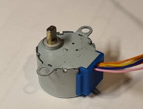
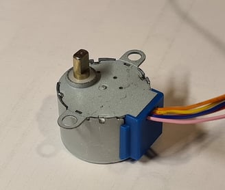
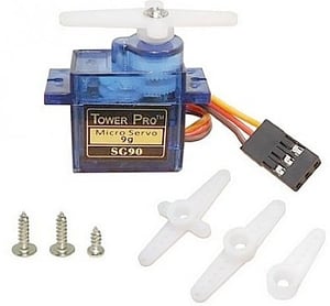
The motors we will use are two common hobbyist motors, the SG90 Micro Servo Motor, and the 28-BYJ-48 stepper motor.

Controlling a Servo Motor
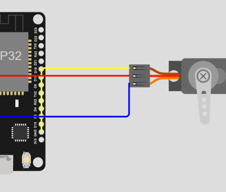
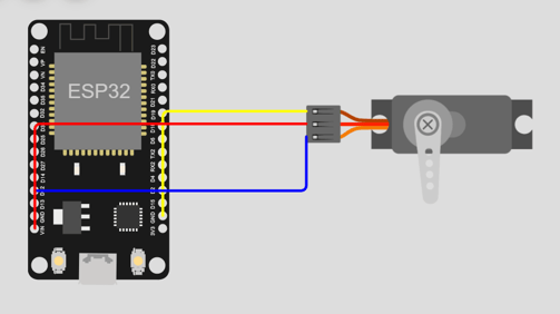
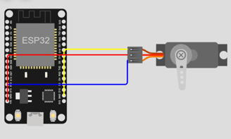
Here is the circuitry necessary to control a SG90 Micro Servo Motor.
Before we can run this code. We will have to install the ESP32Servo library. The preinstalled Servo library cannot be used with ESP32 boards. Go to "Library Manager", search for ESP32Servo, and click install.
The first line includes the ESP32Servo.h library. Libraries are pre-written collections of code that provide additional functionality to your program. In this case, ESP32Servo.h is a library that allows you to control servos using an ESP32 board.
Intro to ESP32 Microcontrollers
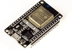
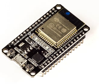
The ESP32 is a versatile and affordable microcontroller developed by Espressif Systems. It has two cores for multitasking and features built-in Wi-Fi and Bluetooth connectivity. The ESP32 is commonly used in IoT projects, home automation, wearables, robotics, and industrial automation. It can be programmed using Arduino IDE and has various development boards available. The active community provides ample support and resources for users.
Why ESP32?
Looking for a new hobby to pick up? Want to create devices that help in daily life? Learning how to leverage microcontrollers is the perfect way to build both hardware and software skills. Programming is needed to control different components, and microcontrollers like the Arduino and ESP32 offer a great entry point for beginners. The possibilities are endless, from smart home automation, to monitoring systems, and robotics.
A microcontroller is a small computer on a single integrated circuit (IC) chip that contains a processor core, memory, and programmable input/output peripherals. It is designed to perform specific tasks and is widely used in various electronic devices and systems.
In this article, we will look over the basic setup of the ESP32 Microcontroller and the Arduino IDE, and program servo and stepper motors that can be used a wide range of projects.


Intro to Motors on the ESP32
Controlling a Stepper Motor
Now lets experiment with the stepper motor.
Setup in Arduino IDE
The Arduino IDE(Integrated Development Environment) enables us to communicate with a microcontroller and upload programs on to it. To enable connection with a ESP32 board, there will be additional steps.
Install the Arduino IDE:
Download and install the Arduino IDE from the official website (https://www.arduino.cc/en/software).
Add ESP32 Board Support:
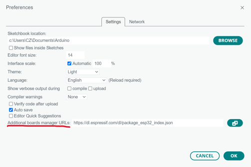
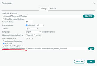
Open the Arduino IDE and go to "File" > "Preferences."
In the "Additional Boards Manager URLs" field, add the following URL: (https://dl.espressif.com/dl/package_esp32_index.json)
Click "OK."
Install ESP32 Board Package:
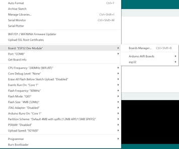
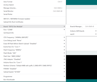
Go to "Tools" > "Board" > "Boards Manager."
Search for "esp32" and install the "esp32" board package.
Select the ESP32 Board:
Go to "Tools" > "Board" and select the appropriate ESP32 board from the list.
Connect ESP32 to Computer:
Plug in the ESP32 board to your computer using a USB cable.
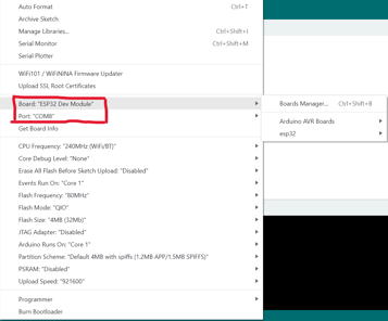
Configure Port:
Go to "Tools" > "Port" and select the correct serial port for the connected ESP32.
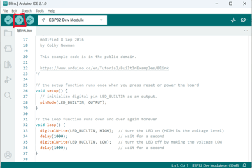
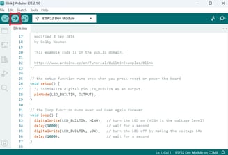
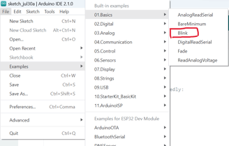
Test the Setup:
To test the setup, upload a simple program. For example, use the "Blink" example from "File" > "Examples" > "01.Basics" > "Blink."
Click on the "Upload" button (right arrow) to compile and upload the program to the ESP32.
Verify Upload and Blink:
Once uploaded successfully, you should see the built-in LED on the ESP32 board blinking.
Congratulations! Your ESP32 is now set up and ready to be programmed for your projects. You can start experimenting with various sensors, actuators, and communication protocols to build exciting IoT applications and electronics projects.
In the next section, we will look over how to program the ESP32 to utilize motors.
The VIN pin acts as voltage input, and is connected to the middle wire. The ground pin should be connected to the brown wire. The final wire is for PWM, or pulse width modulation, a technique that is used to control the speed or intensity of the motor. It could be connected to any of the digital pins provided on the ESP32 board, but we will use Pin 12 for this example.
The following code will result in the servo turning 180 degrees.
This line declares a variable named myServo of type Servo. The Servo data type comes from the included ESP32Servo.h library and is used to control servo motors.
This is the setup() function, which runs once when the Arduino board starts. In this function, we're using myServo.attach(12); to attach the servo to the pin number 12. This means that the servo will be connected to pin 12 on the ESP32 board.
Controlling the Speed of a Servo Motor
The default speed of the MG90 servo may be too fast or slow for some projects. Unfortunately, there is no argument you can pass in the servo write function to change its speed. Instead, we have to code "for" loops to change the speed of the servo.
In the loop() function, we command the servo to move 180 degrees. Next, the servo is delayed/freezed for 1000 milliseconds, or 1 second. We move the servo -180 degrees, or 180 degrees in the other direction, and delay it for another 1000 milliseconds after the turn. The code in the loop is run continuosly, until you cut off the ESP32 power supply.
Conclusion
The pairing of the ESP32 microcontroller and motors opens up a world of possibilities for creating diverse and innovative projects. With the ESP32's built-in Wi-Fi and Bluetooth capabilities, it becomes easy to integrate motors into IoT applications, home automation systems, and robotics projects. The ESP32's processing power and GPIO pins make it suitable for controlling various types of motors, such as stepper motors, servo motors, and DC motors.
From building smart home devices like automated curtains and smart locks to designing autonomous robots and motorized camera mounts, the ESP32 enables seamless communication and control between the microcontroller and motors. Its versatility allows for real-time adjustments, precise positioning, and the implementation of complex motor control algorithms.
Moreover, the ESP32's compatibility with popular development environments like the Arduino IDE and support for various libraries simplifies the programming and implementation of motor-driven projects. The large online community of ESP32 enthusiasts provides a wealth of resources, tutorials, and shared projects, making it easier for hobbyists and developers to learn and explore new ideas.
The ESP32 also has enough RAM for machine learning integration, such as Tensorflow Lite. This makes it a great choice for TinyML applications, a branch of machine learning that focuses on running models on smaller, less powerful devices. Data centers, with gigantic energy input, are growing larger and larger, but the amount of predictions they generate each day cannot come close to the amount of data that is available. If we are able to run models on cheaper, smaller, and less capable devices, imagine how different the world would be today.
Embarking on an exciting journey into robotics and machine learning, I'm challenging myself to create cool projects that push the limits of what's possible. I'll be sharing all the ups and downs on this blog, diving into the world of tech and AI. Let's explore the wonders of artificial intelligence, build robots that do awesome stuff, and have a blast discovering new things together. Join me on this wild ride of imagination and innovation! Welcome to a world of endless possibilities! 🚀
Subscribe to my newsletter below!
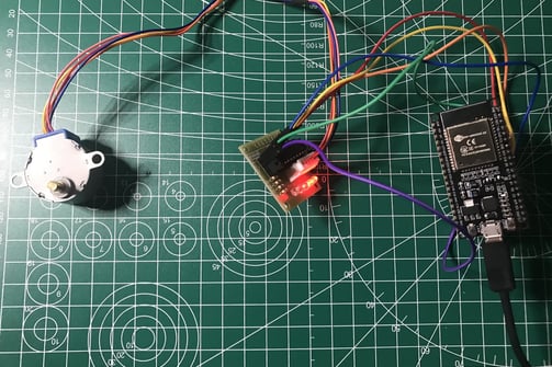
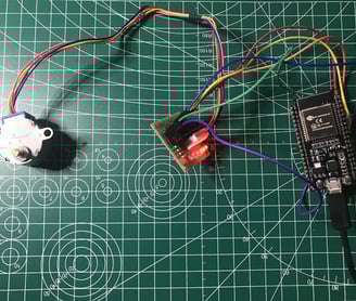
In order to utilize the 28-BYJ-48 stepper motor effectively, the first step is to select an appropriate motor driver capable of handling its current and voltage requirements. Motor drivers are crucial as they supply the motor with high power through a small voltage signal from a microcontroller. The ULN2003 stepper motor driver is a common choice, often included in starter kits and frequently paired with the 28-BYJ-48 motor. Once the motor driver is chosen, understanding the wiring and pinout is essential to correctly connect the components, preventing any potential damage. Additionally, it's necessary to use a suitable power supply that meets the motor driver and motor's voltage and current specifications.
The following code allows the stepper to turn clockwise.
Instead of importing the ESP32Servo library, we will use Stepper. It is already built into the Arduino IDE, so we don't need to worry about installation.
The only changes we make are in the loop() function. The first loop moves the servo in the clockwise direction, and the second loop moves it in the counterclockwise direction. In both loops, during each iteration, the servo moves one degree, and delays for 15 milliseconds. The delay between each movement is the key for controlling the servo speed. Try experimenting with different values!
In the loop() function, we command the servo to step 2048 times by including stepsPerRevolution as an argument. We pause for one second before stepping the same numbers of times in the opposite direction. After the counterclockwise rotation, there is another one second delay.
Setting the speed of a stepper motor is more straightforward compared to a servo motor. We do so in the setup() function. The speed is measured in rotations per minute, and the 28-BYJ-48's maximum is around 10-15 RPM.
In the following lines, we intialize a stepper motor. It has 2048 steps per revolution and is connected to the Arduino using pins 19 (IN1), 18 (IN2), 5 (IN3), and 17 (IN4). The "myStepper" instance is created to control the motor. By adjusting the coil connections in the Stepper constructor or using other control commands, you can control the direction and number of steps the motor rotates, allowing you to create various precise movements for your projects.
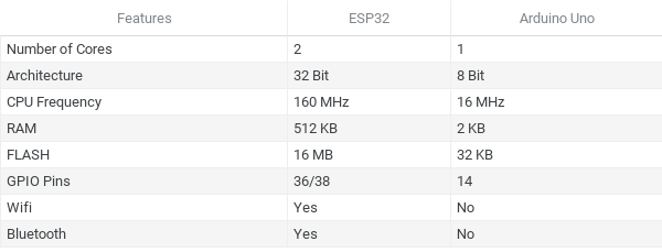
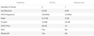
Hopefully, now you have learned how to incorporate motors in your projects. The code used is also appliable to the Arduino boards. However, you won't be able to use pins 17, 18, and 19 because the Arduino only has 14 GPIO pins.
The chart above shows a comparison between the ESP32 and Arduino Uno boards. The price of an Uno is around double the ESP32, but includes less features. The ESP32 boasts wireless and bluetooth connectivity, and greater RAM. Difference in size between the microcontrollers are also substantial. The ESP32 is half the size of the Uno, making it more versatile.